The following outlines the ” Best Practices” for the Flowers Sustainability projects. Please review and let us know if you have any questions or concerns regarding these practices or procedures.
Dear Contractor,
I hope this message finds you well. We are pleased to present the support package tailored for the Flowers Sustainability Project. Your thorough review of the attached documentation is highly appreciated, and we welcome any inquiries or clarifications you may have.
The support package is structured into the following sections to facilitate a comprehensive understanding of the project:
1. Introduction / Overview
2. Sample Installation Diagram
3. Details
a. Water Meters
b. Power Meters
4. Best Practices
5. Specifications
Introduction / Overview
The successful execution of this project necessitates the fulfillment of specific tasks outlined in the following list. These tasks are assigned to the electrical contractor for completion:
1. Provide and run all conduit between device locations.
2. Provide and install all branch circuits between device locations
.3. Provide, test, and label all network connections between devices.
4. Label all conductors and cables per specifications.
5. Install control cabinets provided by Higgins Electric.
6. Install water meters per the specifications.
7. Install power meters and supporting hardware, such as current transformers.8. Provide as-built red lines updates for plant sustainability drawings.
Notes:
1. For each water meter installation, a 10”x 10”x 6” enclosure housing the IO Link Master will be provided. The panel must be mounted within 30 ft of the meter(s), and conduit needs to be run between the panel and meter location. Up to four water meters can be connected to each control panel, allowing for logical device placement in proximity. The IO Link Master panel will be powered over a POE network connection, with the IO Link Master Cat 6 connection running to the Bakery of the Future POE Switch.
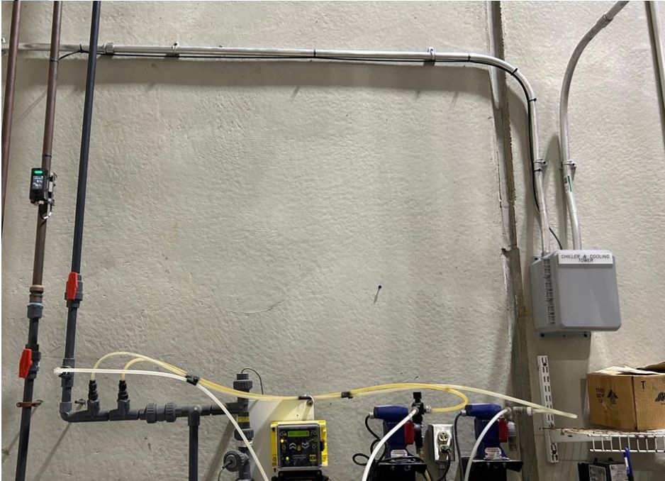
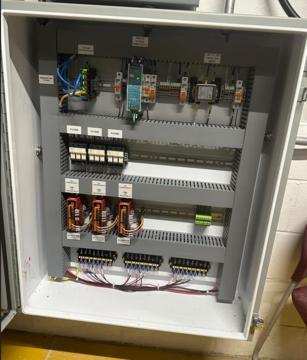
2. Each power meter installation will be accompanied by a control cabinet in a wall-mount enclosure. The control cabinet, which houses fuse blocks for power connections and shorting blocks for current transformers, will be provided. If the voltage is less than 500Vac line to line, no potential transformers will be needed. The contractor is responsible for installing split core (solid core if split core is unavailable) current transformers and terminating them to shorting blocks inside the control cabinet. Control drawings will be provided. The control cabinet will require a network connection via Cat 6 cable to the nearest Bakery of the Future POE Switch.
Your attention to these details is crucial for the successful implementation of the Flowers Sustainability Project. We look forward to your feedback and collaboration throughout this endeavor.
Should you have any questions or require further clarification, please do not hesitate to reach out.
Best regards
,Mike Crawford
Automation Manager
Higgins Electric
Dothan, AL 36301
Phone: 1-334-793-4859
Cell: 1-334-701-9792
Email: mikecrawford@higginselectric.com
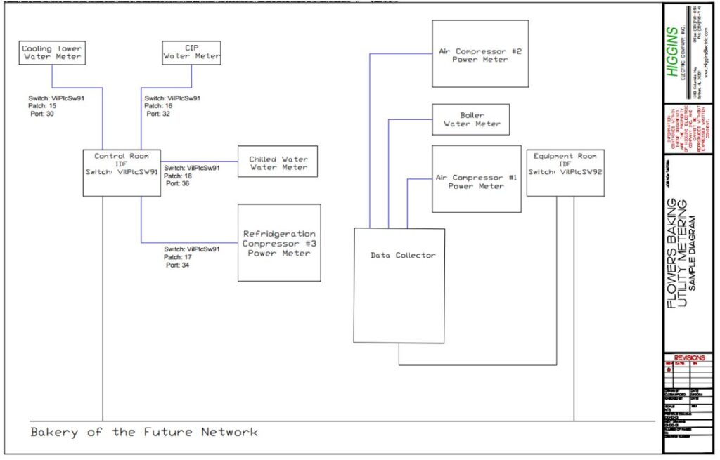
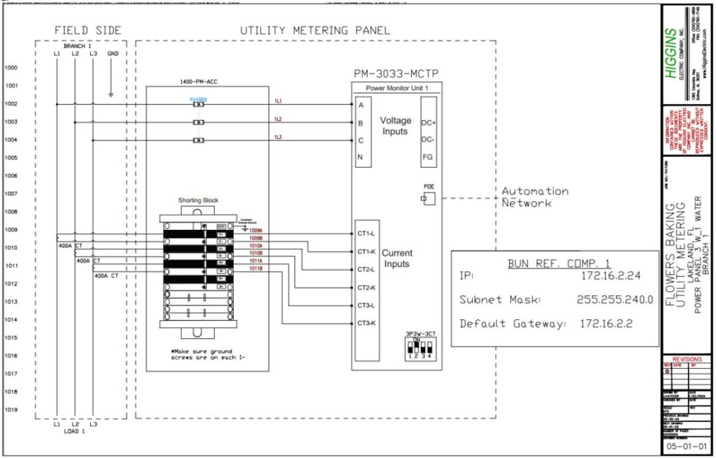
Sample Installation Diagram
The following are sample diagrams used in the installation of the power meters, water meters, and interconnecting network. Additional documents attached.
1. Network overview sample. This is only a sample diagram.
2. Power Meter Sample3. Water Meter Sample
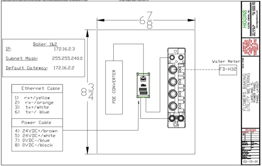
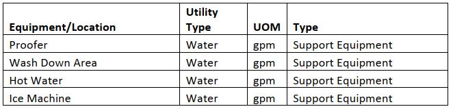
Water Meter Details
I would like to bring to your attention the current target locations outlined for water meter installations. It has been identified that some of these locations pose challenges either from an economic or logistical standpoint, rendering them unattainable in this phase.
Specifically, the Dough Mixer and Sponge Mixer ingredient water requirements are already accounted for through our batching system. To obtain accurate values for the water used in these processes, we propose utilizing the batching system’s capabilities to query and retrieve the necessary data. This approach eliminates the need for installing physical meters at these locations.
By leveraging the existing batching system, we can ensure the precision of the information without incurring unnecessary costs or introducing complexity to the installation process.
Target Locations
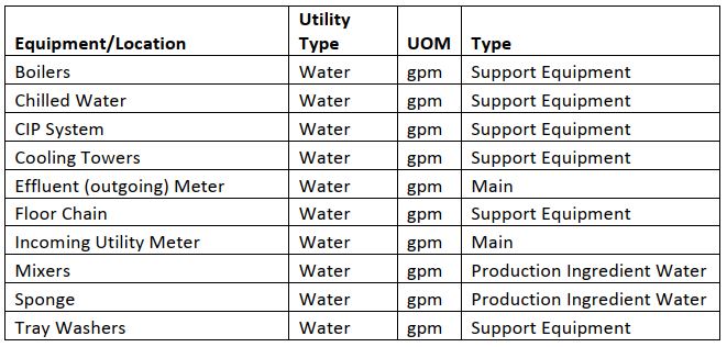
Any additional locations that are potentially high users of water may also be added such as the following. This is a plant by plant assessment.
Power Meter Details
Our objective is to gather power and energy metrics from the specified locations, utilizing an ICP power meter or an equivalent device from another manufacturer.
The installation process involves placing appropriately sized current transformers on each leg of the phase, accompanied by a voltage input. The ICP Power Meter itself is then connected to the “Bakery of the Future” network through a Cat 6 Ethernet cable. These devices draw power through the POE (Power over Ethernet) provided by the BOF switch, ensuring seamless connectivity to the end device, i.e., the ICP Power Meter.
It is of utmost importance to emphasize the correct installation of current transformers (CTs). This involves meticulous attention to polarity and the application of proper techniques. When connecting CTs under power or adjusting conductors, it is imperative to utilize shorting blocks to ensure safety and prevent damage to the current transformer.
Your adherence to these installation guidelines is crucial for the accurate and efficient collection of power information. If you have any questions or require further clarification, please do not hesitate to reach out. We appreciate your commitment to maintaining the integrity of the installation process.
Target Locations
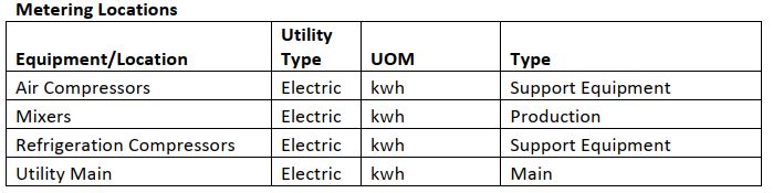
As the Utility Main is often difficult to arrange a plant shutdown to install CT’s it will be based on plant-to-plant assessment. Currently, we have not installed metering equipment on the Utility Mains. However, it remains on the list and a target of opportunity.
Best Practices
The following is a compilation of best practices and lessons learned regarding the data concentrator, power meter, water meter and networking. This is not all inclusive but some of the main issues we have ran into.
Water Meter
It is important to install the water meter per the manufacturer’s installation instructions. However, the following are some recommendations that should be followed when possible.
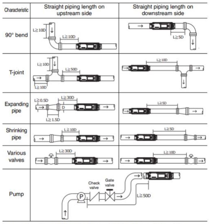
1. Water meters should be installed where there is adequate room on either side of meter. The general rule of thumb is to have at least 5 times the pipe diameter prior to and after the meter to allow for proper operation.
Note: To improve the measurement accuracy, it is recommended that the straight sections of pipe, with the lengths based on the table below, exist both upstream and downstream of the unit: (D: Pipe outer diameter)
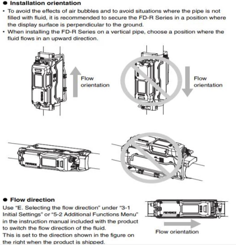
2. It is also advantageous to mount the meter with the correct orientation such that the meter has the best chance to accurately measure the flow
FD-R-50 & 80 Installation practice. The FD-H10,20 & 32 will work in both horizontal and vertical configurations.
Insulation removal
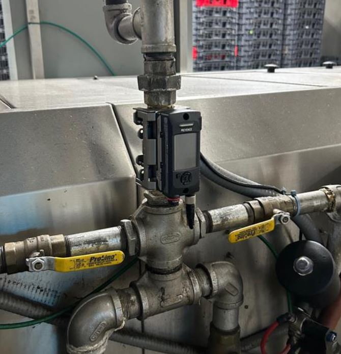
The following is a good installation, where only the amount of insulation needed to install the meter was removed.
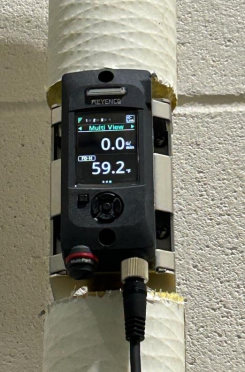
The following is a good installation of the meter, however the contractor had to unwire the unit to install a cable gland in the TEE. Per the specifications, all cable will have the proper connecting devices IE… Cable glands. Good wiring practices must be maintained.
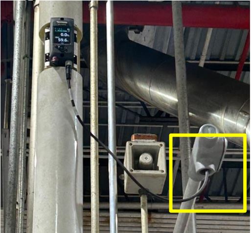
Cabling
Short runs of cable between the control cabinet and the meter that are exposed are acceptable. However, the cable must be protected from damage and properly supported. If you support with a ty-wrap or other cabling system do not over tighten the support. This can damage the cable.
Figure 1
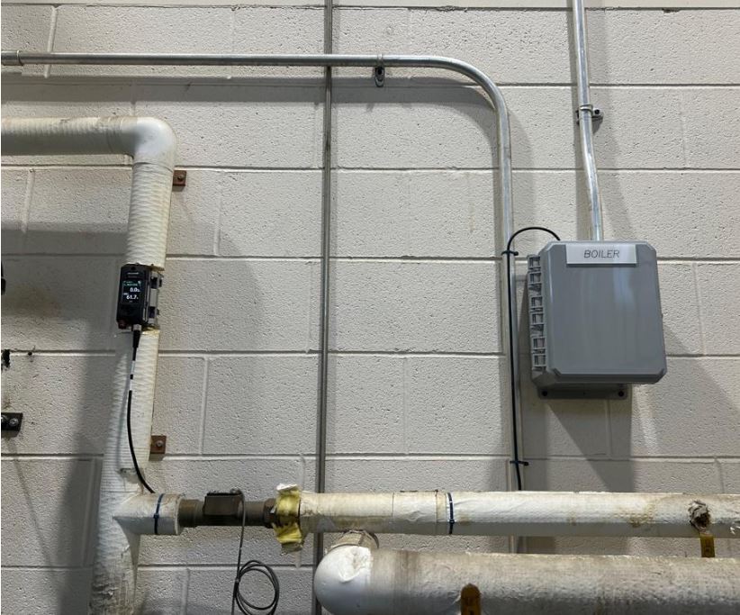
Figure 2
The following is an example of a poorly installed meter. The rule of thumb (5 times the diameter of pipe before and after meter) was not followed. This is not the correct location to install this meter. The disruptions in the pipe will cause the meter to read an erroneous value.
Power Meter
Good practices for installing the power meter cabinets and current transformers. It is imperative to install the power meter CT’s in a manner that will allow the cable(s) passing through the CT to be as close to the center as possible. If it is a Split Core CT it must close and snap lock to ensure it is properly connected around cabling. It must be installed with the correct polarity to the flow of current in the conductor. Failing to install properly will require it to be removed and reinstalled. The following warning is included in every power metering panel.
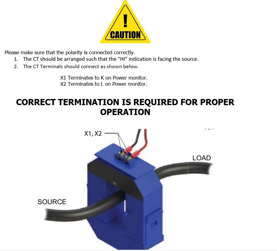
Short CT conductors when doing maintenance on system or moving conductors. Failure to short CT could result in damage!
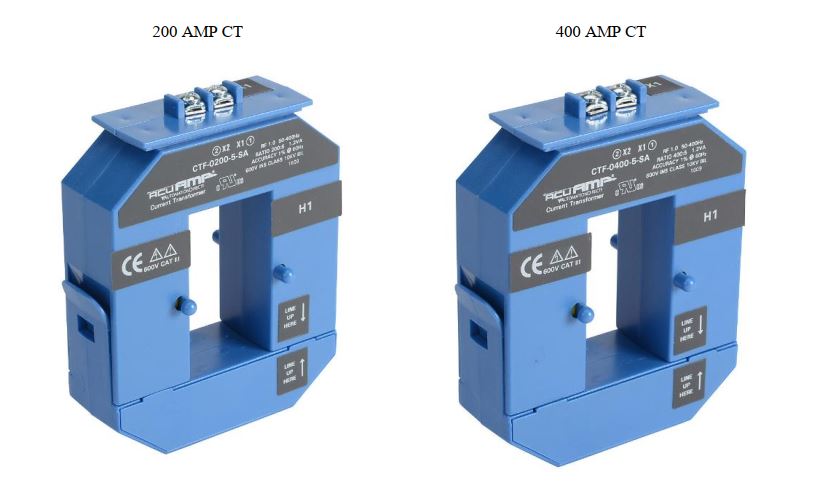
Care must be taken to ensure the correct size CT is installed on the motor circuit. Example, you cannot install a 200 amp CT on a motor circuit pulling 275amps. This will damage the CT. The CT amperage is stenciled on the side of the CT. In the instance of a motor pulling 275 amps we would install a 400 amp CT. In addition all phases must have the same size CT installed.
The following are good examples of installing CT’s. This is both Split Core and Solid Core.
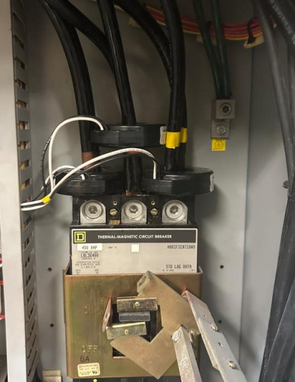
Split Core installation with voltage input installed.
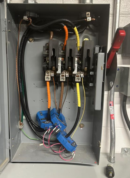
The following is a properly installed power meter cabinet. The CT’s are properly terminated to shorting terminal blocks and labeled. The Voltage inputs are terminated on the fuse blocks. This cabinet supports three power meters
The power inputs and conductors from the CT’s can be run in the same conduit from the meter cabinet to the disconnect or compressor, etc.
Typical Cabinet install.
Specifications
The following pages outline the specifications for the sustainability install. These specifications are the guide and rule and must be adhered to. The following are some things we have see in the field that must be avoided.
- 1. No cable glands
- 2. Improper strapping
- 3. Running Data Concentrator from receptacle circuit rather than its own branch circuit.
- 4. No labeling on Category 6 cables
- 5. Cables installed, terminated, and not tested. We have had to bring contractors back out to terminate cablesbecause they were never tested and was incorrectly crimped.
- 6. Ethernet cables ran to Flowers business switches rather than the Bakery of the Future switches.
- 7. Multiple amperage CT’s installed on same motor circuit.
- 8. Water Meters installed on the wrong pipes or in the wrong location (close to nipples, tee’s and 90 degree elbows).
These are just a few. It is important to read and understand the specifications to ensure that both the install and wiring practices are followed. If you have any questions, please feel free to contact us for further information or explanation.
Flowers Sustainability Construction Specifications